
CNC machining is an essential process for mechanical engineers to understand because it bridges the gap between digital designs and real-world components. It enables the precise and repeatable production of complex geometries, turning CAD models into high-quality parts with tight tolerances. By understanding CNC capabilities and limitations, engineers can design parts that are easier and more cost-effective to manufacture, avoiding features that may be difficult or impossible to machine. This knowledge also improves collaboration with manufacturing teams, ensuring that designs are optimized for the chosen materials, tooling, and production methods. Ultimately, familiarity with CNC machining allows mechanical engineers to create designs that can be manufactured efficiently, accurately, and at scale.
The purpose of Design for Manufacturing (DFM) in CNC machining is to optimize a part’s design so it can be produced efficiently, cost-effectively, and with high quality using CNC processes. DFM helps identify and address potential manufacturing challenges early in the design phase, reducing production time, minimizing material waste, simplifying machining operations, and ensuring that the final product meets functional and tolerance requirements. Ultimately, DFM in CNC machining aims to streamline the workflow between design and manufacturing, improving reliability and lowering overall costs.
In the following article, we will dive into the world of CNC machining, exploring its principles, capabilities, and practical applications. We will examine how this technology can be optimized and adapted to meet our specific needs, enabling us to achieve greater precision, efficiency, and flexibility in manufacturing.
CNC Technologies Overview
CNC machining comes in several types, each designed for different shapes, materials, and manufacturing needs. The main categories include CNC milling, where rotating cutting tools remove material from a workpiece to create complex shapes; CNC turning (lathe), which spins the workpiece while a cutting tool shapes it, ideal for cylindrical parts; CNC drilling, focused on creating precise holes; and CNC grinding, which uses abrasive wheels to achieve very fine finishes and tight tolerances.

Milling
CNC milling is a machining process that uses computer-controlled rotating cutting tools to remove material from a stationary workpiece, creating precise shapes, features, and surfaces. It is one of the most versatile forms of CNC machining, capable of producing complex 2D and 3D geometries from a wide range of materials, including metals, plastics, and composites. Milling machines can operate along multiple axes—commonly three, but often four or five in advanced setups—allowing intricate contours, undercuts, and detailed surface finishes to be achieved with high accuracy. By translating CAD designs into precise tool paths, CNC milling delivers repeatable results, making it essential for both rapid prototyping and high-volume production in industries such as aerospace, automotive, and medical manufacturing.
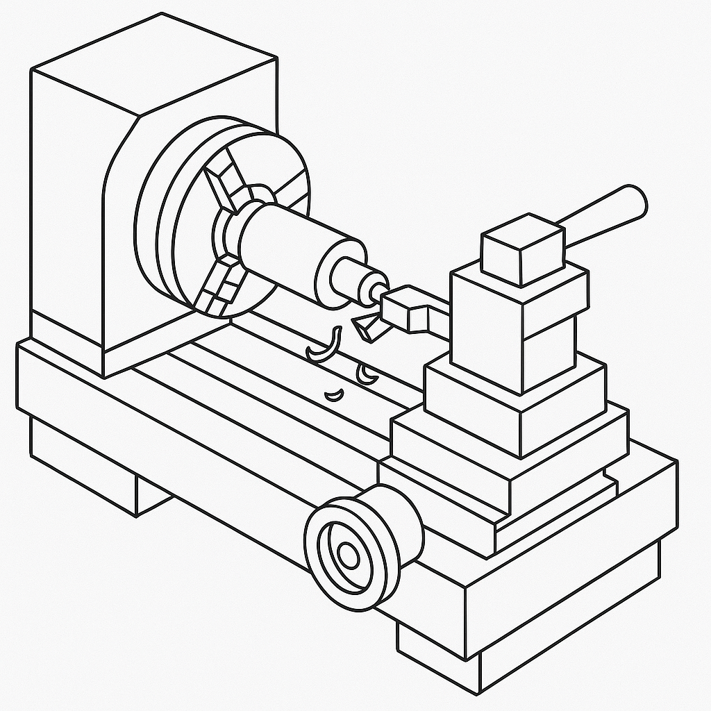
Turning
CNC turning is a machining process in which a computer-controlled lathe rotates a workpiece while a stationary cutting tool removes material to create precise cylindrical shapes. It is widely used for producing parts such as shafts, bolts, and bushings, as well as more complex components with tapers, threads, and grooves. CNC turning offers high accuracy, excellent surface finishes, and the ability to produce parts quickly and consistently, making it ideal for both prototyping and mass production. Advanced CNC lathes, including multi-axis and live tooling machines, can perform additional operations such as milling, drilling, and tapping without removing the part from the machine, increasing efficiency and reducing setup time. This combination of precision, speed, and versatility makes CNC turning a key manufacturing process across industries like automotive, aerospace, and medical devices.
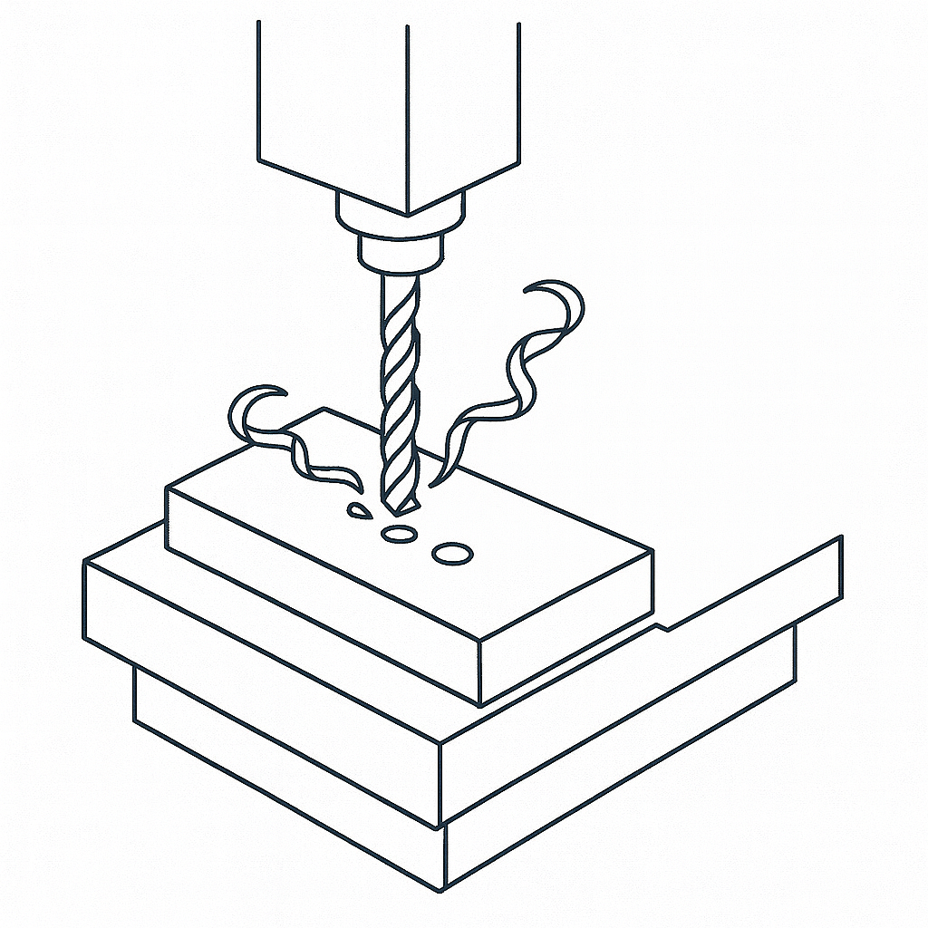
Drilling
CNC drilling is a machining process that uses computer-controlled movements to create precise, repeatable holes in a workpiece. Unlike manual drilling, CNC drilling automates tool positioning, feed rate, and depth, ensuring consistent accuracy across multiple parts. This process is commonly used for producing holes of various sizes, patterns, and depths in materials such as metals, plastics, and composites. CNC drilling machines can also perform specialized operations like counterboring, countersinking, and tapping, allowing for complete hole preparation in a single setup. By integrating drilling into multi-axis CNC machines or machining centers, manufacturers can streamline production, reduce errors, and achieve higher throughput, making CNC drilling an essential process in industries ranging from electronics and automotive to aerospace and medical manufacturing.
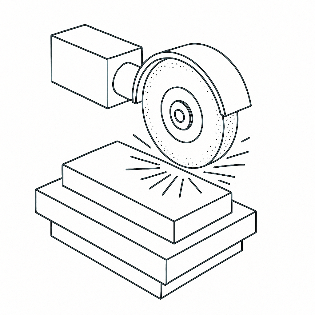
Grinding
CNC grinding is a precision machining process that uses computer-controlled abrasive wheels to remove small amounts of material and achieve extremely tight tolerances and fine surface finishes. Unlike cutting tools, grinding relies on thousands of abrasive particles on the wheel’s surface, making it ideal for finishing hardened materials such as tool steel, ceramics, and carbides. CNC grinders can perform a range of operations, including surface grinding, cylindrical grinding, and centerless grinding, depending on the part geometry and requirements. The automated control ensures consistent accuracy, repeatability, and the ability to create complex shapes or contours that would be difficult to achieve with conventional machining. CNC grinding is widely used in industries like aerospace, automotive, and medical devices, where precision, durability, and surface quality are critical.
Material Selection Considerations
Material selection is one of the most critical decisions in CNC machining, directly impacting manufacturability, cost, and final part performance. Choosing the right material can simplify machining processes, reduce cycle times, and improve tool life, while the wrong choice can lead to excessive costs, part defects, or production delays.
Metals vs. Plastics
CNC machining can accommodate a wide range of materials, but the two broad categories are metals and plastics.
- Metals: Commonly machined metals include aluminum, steel (carbon and stainless), brass, titanium, and alloys such as Inconel or copper alloys. Metals generally offer higher strength and durability but often require slower machining speeds and more robust tooling.
- Plastics: Materials like ABS, Delrin (acetal), nylon, and polycarbonate are easier to machine due to lower hardness and melting points. Plastics typically allow faster cycle times but may require special considerations for thermal expansion or surface finish.
Machinability Ratings
Machinability is a measure of how easily a material can be cut using CNC processes. It depends on factors such as hardness, toughness, thermal conductivity, and chemical composition.
- Materials like free-machining aluminum alloys or brass often have high machinability ratings, allowing faster cutting speeds and longer tool life.
- Hard steels, titanium, or exotic alloys usually have lower machinability, resulting in slower feed rates and increased tool wear.
Understanding machinability helps optimize tool selection, cutting parameters, and ultimately lowers manufacturing cost.
Impact of Material Choice on Tooling and Cycle Time
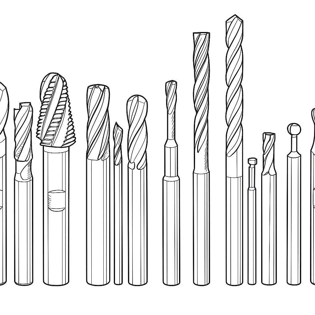
- Tooling: Different materials require different cutting tools (carbide, HSS, coated tools) and tool geometries. For example, harder materials often need tools with wear-resistant coatings or special flute designs.
- Cycle Time: Softer, easier-to-machine materials generally result in shorter cycle times. Conversely, tougher materials may require multiple passes, slower feeds, and coolant use to avoid tool damage or thermal distortion.
Other Material Factors
- Thermal Properties: Materials with high thermal expansion may deform during machining, impacting tolerances.
- Surface Finish Requirements: Some materials machine to a smoother finish naturally, while others need additional post-processing.
- Cost and Availability: Some exotic alloys may increase lead time and price.
Careful consideration of material properties early in the design phase ensures that CNC machining processes remain efficient and cost-effective without compromising part performance.
Tolerances & Dimensional Accuracy
Tolerances define the allowable variation in a part’s dimensions and are critical in ensuring proper fit, function, and interchangeability. In CNC machining, understanding achievable tolerances and how to specify them effectively can greatly impact manufacturing cost, lead time, and part quality.
Standard Achievable Tolerances in CNC Machining
CNC machines can produce parts with high precision, but achievable tolerances depend on factors such as material, part size, machine type, and setup. Typical tolerance ranges are:
- General machining: ±0.1 mm (±0.004 inches)
- Precision machining: ±0.01 mm (±0.0004 inches) or better for smaller features
- Ultra-precision machining: down to ±0.005 mm (±0.0002 inches) on specialized equipment
Most standard CNC shops routinely hold tolerances around ±0.02 mm (±0.0008 inches) for features smaller than 50 mm.
Cost Implications of Tight Tolerances
Tighter tolerances increase machining complexity, often requiring:
- Slower cutting speeds and feeds to maintain accuracy
- Additional finishing operations such as grinding or honing
- More frequent tool changes and tool wear monitoring
- Increased inspection and quality control efforts
Designers should apply tight tolerances only to features critical for function, and allow looser tolerances elsewhere to reduce cost.
Geometric Dimensioning and Tolerancing (GD&T) for CNC
GD&T provides a standardized system to communicate allowable variations in shape, orientation, and location of features beyond simple linear dimensions. Applying GD&T can:
- Clarify critical features for machinists and inspectors
- Reduce over-specification and unnecessary tight tolerances
- Allow flexibility in manufacturing while ensuring functionality
Examples include flatness, perpendicularity, and position tolerances, which guide machinists on how precise features must be relative to each other.
Best Practices for Specifying Tolerances in CNC Design
- Function-driven: Focus tight tolerances on mating surfaces and critical features only.
- Avoid over-tolerancing: Don’t specify tighter tolerances than the functional requirement.
- Use standard tolerance classes: Refer to ISO or ANSI standards for general tolerance guidelines.
- Communicate clearly: Use proper notation and consistent units on drawings.
- Discuss with manufacturers: Early collaboration helps align design intent with realistic machining capabilities.
By carefully specifying tolerances, designers can balance performance with manufacturability, achieving cost-effective and high-quality CNC machined parts.
Surface Finish Requirements
Surface finish refers to the texture and smoothness of a part’s surface after machining. It affects not only the part’s aesthetic appeal but also its functional performance, such as friction, wear resistance, sealing, and fatigue life. Properly specifying surface finish is essential to achieving the desired balance between quality and manufacturing cost.
Standard Surface Finishes Achievable by CNC Machining
CNC machining typically produces surface finishes ranging from approximately 1.6 to 6.3 micrometers Ra (roughness average) without secondary operations. The exact finish depends on factors such as:
- Cutting tool type and condition
- Machining parameters (speed, feed, depth of cut)
- Material properties
- Machine rigidity and condition
For example, aluminum often machines to a smoother finish than stainless steel under similar conditions.
Factors Affecting Surface Finish
- Tool geometry: Sharp, well-maintained tools produce finer finishes. Tool wear can increase surface roughness.
- Feed rate and spindle speed: Lower feed rates and higher spindle speeds usually improve finish but may increase cycle time.
- Coolant use: Proper lubrication reduces heat and improves surface quality.
- Material hardness: Softer materials may smear or deform, affecting finish.
Secondary Processes to Improve Surface Finish
If the required surface finish is smoother than standard CNC machining can provide, secondary processes may be applied:
- Polishing: Mechanical or chemical polishing to reduce roughness and improve appearance.
- Grinding: Abrasive grinding for tight tolerance and fine finish on hardened surfaces.
- Coatings: Anodizing, plating, or painting can enhance surface properties and aesthetics.
- Burnishing: Cold working the surface to improve hardness and smoothness.
These processes increase manufacturing time and cost and should only be specified when functionally necessary.
Specifying Surface Finish in Design
- Use standard symbols and units (e.g., Ra in micrometers or microinches) on technical drawings.
- Apply varying finishes strategically — specify finer finishes only on mating or visible surfaces, and allow rougher finishes elsewhere.
- Consider functional requirements like sealing, wear, or aesthetics when defining finish values.
- Consult with manufacturers to determine cost-effective finish targets aligned with machining capabilities.
By thoughtfully considering surface finish requirements early in design, engineers can optimize the tradeoff between manufacturing cost, time, and part performance.
Design Geometry for CNC Efficiency
Optimizing part geometry is fundamental to ensuring efficient, cost-effective CNC machining. Well-considered design features reduce machining time, minimize tool wear, and simplify setups, ultimately improving overall manufacturability without compromising part function.
Avoid Sharp Internal Corners
CNC milling tools are typically round, so sharp internal corners are impossible to machine directly. Instead, incorporate fillets or radii matching the tool diameter to facilitate smooth tool paths and reduce stress concentrations. This avoids costly secondary operations such as EDM or manual finishing.

Maintain Minimum Feature Sizes
Features must meet minimum size requirements compatible with standard tooling:
- Holes: Typically no smaller than 1.5 mm diameter to avoid specialized drill bits.
- Slots and pockets: Should have widths larger than the smallest standard end mill (usually around 2–3 mm).
- Wall thickness: Maintain sufficient thickness (generally >1 mm for metals) to prevent deformation and vibration during machining.
Adhering to these limits reduces the need for custom tools and improves machining stability.
Ensure Tool Accessibility
Design parts so cutting tools can access all features without obstruction. Avoid deep, narrow cavities or undercuts that require special tooling or multiple setups. If undercuts are necessary, consider using multi-axis machining or designing features that simplify tool approach.
Reduce Unnecessary Complexity
Simplify complex geometries that do not add functional value. Excessive detail increases machining time and risk of errors. Use symmetry and modular design where possible to allow easier fixturing and reuse of tool paths.
Consider Draft Angles
Adding slight draft angles (1–3 degrees) on vertical walls can facilitate chip evacuation and reduce tool pressure, especially in deep pockets. This improves surface finish and reduces tool wear.
By integrating these geometric principles into design, engineers can significantly enhance CNC machining efficiency, reduce costs, and improve part quality.
Fixturing & Workholding in DFM
Fixturing and workholding are critical components of the CNC machining process. Properly designed parts that facilitate secure and efficient clamping reduce setup time, improve accuracy, and minimize part deformation during machining.
Influence of Part Geometry on Fixturing
The shape, size, and features of a part determine how it can be held during machining. Flat, stable surfaces are ideal for clamping, while irregular or thin-walled parts may require custom fixtures or supports. Including features such as flat pads, datum surfaces, or locating bosses in the design can simplify fixturing.
Designing for Easy Clamping
- Provide sufficient flat or parallel surfaces for clamps or vises.
- Avoid placing critical features where clamps will contact, to prevent damage or distortion.
- Design symmetrical parts where possible, allowing multiple fixturing orientations.
Minimizing the Number of Setups
Each setup involves repositioning and reclamping the part, increasing cycle time and risk of errors. Designing parts to allow machining multiple features in a single setup—such as using through-holes for locating pins or symmetrical features—can significantly improve efficiency.
Considering Workholding Constraints
- Thin walls or flexible features may require support fixtures or backing material to prevent vibration or bending.
- Part size must be compatible with machine work envelope and fixturing equipment.
- Material hardness affects clamping force needed and potential deformation.
Incorporating fixturing considerations into early design stages enables smoother production, higher precision, and lower costs.
Tool Path & Machine Limitations
Understanding CNC machine capabilities and tool path strategies is essential to designing parts that are efficient to manufacture and cost-effective.
Axis Capabilities and Their Impact
CNC machines come in various configurations:
- 3-Axis machines: Most common, allow movement along X, Y, and Z axes. Suitable for simple to moderately complex geometries.
- 4-Axis machines: Add rotational movement around one axis, enabling machining of cylindrical parts or complex contours in a single setup.
- 5-Axis machines: Offer movement along three linear and two rotational axes, allowing complex parts with undercuts and intricate features to be machined efficiently.
Designers should consider the machine type when specifying geometry. Parts requiring multi-axis machining may increase cost due to machine time and programming complexity.
Tool Reach and Deflection Limits
Long, slender cutting tools are prone to deflection, causing poor surface finish and dimensional inaccuracies. Designs with deep cavities or tall features must consider:
- Minimizing tool length-to-diameter ratio
- Using larger tool diameters where possible
- Avoiding deep, narrow pockets that necessitate long tools
Reducing tool deflection enhances part quality and reduces scrap.
Minimizing Tool Changes
Frequent tool changes increase cycle time and setup complexity. Design features to:
- Group similar machining operations together
- Use standard tool sizes
- Avoid complex geometries that require specialized tools
This streamlines programming and machining, reducing lead times.
Optimizing Tool Paths
Efficient tool paths reduce machining time and wear. Design features that allow smooth, continuous cutting motions without frequent stops or direction changes. Avoid abrupt geometry changes or intricate details that force complex tool paths.
By aligning part design with machine and tooling capabilities, engineers can optimize production efficiency and cost in CNC machining.
Cost Reduction Strategies
Designing with cost efficiency in mind is essential for competitive manufacturing. By applying thoughtful strategies, designers can reduce CNC machining expenses without compromising part quality or function.
Design for Batch Production
Producing parts in batches leverages economies of scale. While initial setup and programming costs may be higher, spreading these costs over larger quantities significantly reduces the per-part price. Designing parts that are easy to fixture and machine consistently aids batch production efficiency.
Simplify Geometry to Reduce Machining Time
Complex features, intricate contours, and multiple setups increase machining time and cost. Simplifying part geometry by:
- Using standard hole sizes
- Avoiding unnecessary tight tolerances
- Minimizing sharp corners and undercuts
can drastically reduce cycle times and tooling requirements.
Select Materials for Machinability and Cost
Choosing materials with high machinability reduces tooling wear and speeds up cutting operations. For example, aluminum and brass generally machine faster and more cheaply than hardened steels or exotic alloys. Balancing performance with machinability impacts overall cost.
Minimize Number of Setups and Tool Changes
Each setup requires additional time and introduces potential for errors. Designing parts to be machined fully or mostly in a single setup lowers labor costs and improves accuracy. Similarly, using features that can be machined with standard tooling reduces tool change frequency.
Collaborate Early with Manufacturers
Engaging with CNC shops during the design phase can uncover cost-saving opportunities such as alternative materials, design adjustments for simpler machining, or batch size optimization.
Implementing these strategies allows manufacturers to produce high-quality parts efficiently and economically.
Quality Assurance & Inspection in CNC Parts
Ensuring the quality of CNC machined parts is vital to meet functional requirements and customer expectations. Incorporating inspection considerations into design streamlines quality control and reduces rework or scrap.
Common Inspection Methods
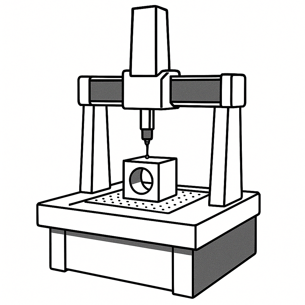
- Coordinate Measuring Machines (CMM): Provide highly accurate 3D measurements of complex geometries. Ideal for critical features and tight tolerances
.
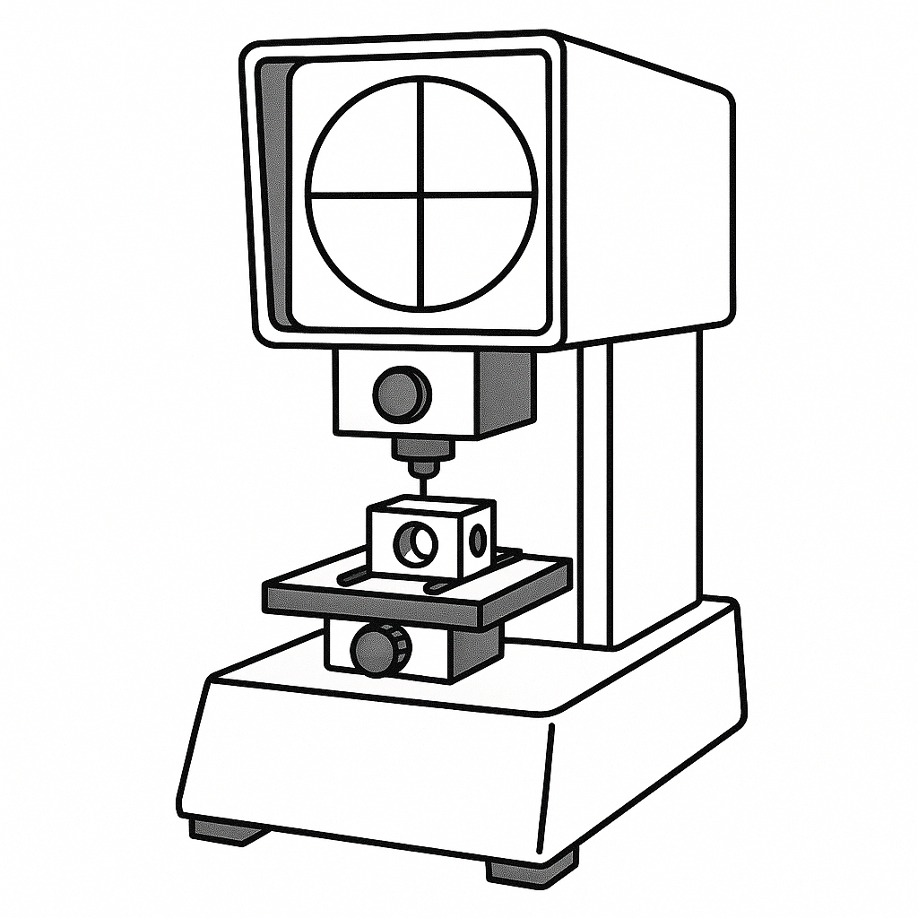
- Optical Comparators: Use magnified visual comparison against CAD profiles for simpler shapes and contours.
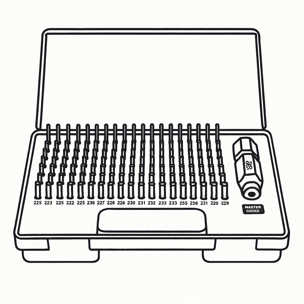
- Calibrated Gauges and Fixtures: Quick, repeatable verification of critical dimensions such as hole sizes and distances.
Designing for Easy Inspection
- Include accessible datum surfaces and reference points to establish consistent measurement setups.
- Avoid overly complex or obstructed features that are difficult to measure.
- Design critical dimensions in locations that allow direct contact measurement rather than inferred or indirect methods.
Inspection Planning
Designers should communicate inspection requirements clearly through drawings and documentation, specifying acceptable tolerances, critical features, and preferred measurement methods. Collaborate with quality teams early to ensure inspection feasibility.
Integrating quality assurance into the design phase promotes reliable production, reduces costs associated with defects, and enhances customer satisfaction
Case Studies / Examples
Real-world examples illustrate how applying DFM principles in CNC machining can significantly improve manufacturability, reduce cost, and enhance quality.
Case Study 1: Optimizing Internal Corners
Problem: A metal bracket initially designed with sharp internal corners required EDM for finishing, increasing cost and lead time.
Solution: Redesign replaced sharp corners with fillets matching the tool radius, allowing standard end mills to machine the part without secondary processes.
Result: Machining time reduced by 30%, tooling costs decreased, and overall lead time shortened by 20%.
Case Study 2: Material Selection Impact
Problem: A prototype used stainless steel, resulting in slow machining and rapid tool wear.
Solution: Switching to an aluminum alloy with similar mechanical properties but higher machinability.
Result: Cycle time cut by 40%, tooling expenses reduced, and part quality improved.
Case Study 3: Reducing Setups Through Symmetrical Design
Problem: A complex housing required four separate machining setups due to asymmetrical features.
Solution: Redesigned for symmetry and incorporated datum features enabling machining multiple faces in a single setup.
Result: Setup time cut in half, reduced cumulative dimensional errors, and lowered overall manufacturing cost.
These examples demonstrate how thoughtful design changes based on DFM principles optimize CNC machining processes and outcomes.
Conclusion & Best Practices Checklist
Applying Design for Manufacturability principles in CNC machining is essential to producing high-quality parts efficiently and cost-effectively. By understanding machining capabilities, material properties, and geometric constraints, designers can optimize their designs to minimize production challenges and expenses.
Key Takeaways:
- Select materials balancing performance and machinability.
- Specify tolerances only where functionally necessary.
- Design features accessible to standard tooling with appropriate radii and dimensions.
- Incorporate fixturing considerations early to reduce setups and improve accuracy.
- Minimize tool changes and optimize tool paths to shorten cycle times.
- Avoid common mistakes such as sharp corners, thin walls, and over-tolerancing.
- Collaborate closely with manufacturers to align design and process capabilities.
- Consider inspection needs in design to facilitate quality control.
Best Practices Checklist for CNC Machining DFM

.png)