In mechanical design, holes are everywhere - mounting, clearance, fasteners, alignment, cooling, and more. Yet despite how common they are, poor hole design is still one of the top causes of cost overruns, part failure, and delays in manufacturing.
This post walks through critical Design for Manufacturing (DFM) best practices related to hole design- covering everything from correct technology selection to tolerancing and cost considerations. Whether you're working in SolidWorks or reviewing a part for production, these principles will help you avoid mistakes and design with manufacturing in mind.
1. Choose the Right Hole-Making Technology
Not all holes are created equal and not all are manufactured the same way. Understanding which process your part will go through is essential.
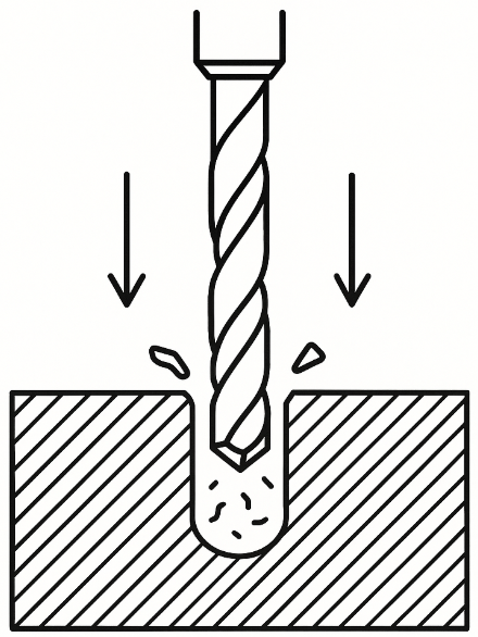
Drilling
Drilling uses a rotating fluted twist drill that advances axially into the material, generating a cylindrical hole via plastic deformation and chip evacuation. The cutting edges shear the material while the chisel point centers the bit. Drill geometry (point angle, helix, flute count) determines performance across materials.
Pros:
- Fast and cost-effective
- Vast tool standardization
- Compatible with almost all materials
Cons:
- Only circular cross-sections
- Lower positional accuracy
- Often needs secondary finishing
When to use:
For general-purpose holes in metals, plastics, Composite or wood. Perfect for tapped holes, clearance holes, and low-precision bores.
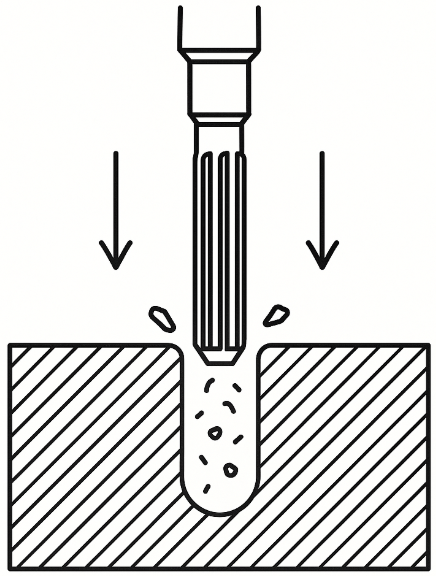
Reaming
Reaming follows drilling with a straight or helical multi-flute tool that removes a small radial layer (~0.2–0.5 mm) to refine diameter and surface finish. It doesn’t correct major misalignment, but it does bring size within ±0.01 mm and enhances concentricity and finish down to Ra < 1.6 μm.
Pros:
- Achieves close tolerances
- Improves roundness and finish
- Minimal tool deflection
Cons:
- Adds costly cycle time and setup
- Can’t fix location errors from drilling
- Only minor material removal
When to use:
Use for holes requiring press fits, bearings, dowel alignment, or smooth sliding fits, especially when surface integrity matters.
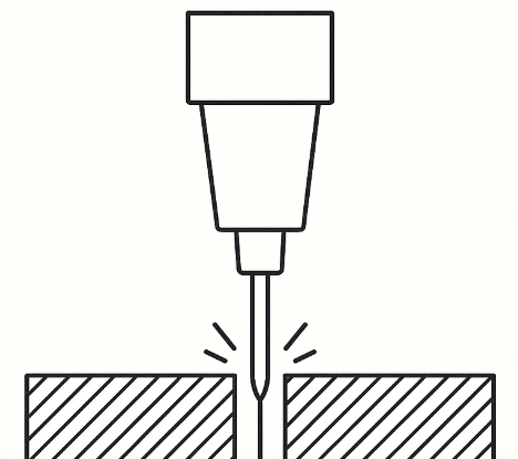
Laser Cutting
Laser cutting focuses a collimated, high-energy beam onto a workpiece surface, where it rapidly melts, vaporizes, or oxidizes material along the beam path. Assist gases (such as O₂, N₂) help with kerf evacuation and cooling. CNC control delivers tight profiles in thin sheet stock.
Pros:
- High accuracy and repeatability
- Excellent for thin metals
- Minimal mechanical force = low distortion
Cons:
- Thickness and geometry limitations
- Creates heat-affected zones (HAZ)
- Can leave tapered holes or dross
When to use:
Use for small-to-medium holes in sheet metal (<6 mm), when part volume or detail density rules out punching.
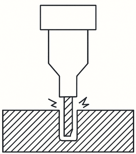
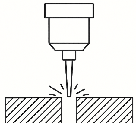
EDM (Electrical Discharge Machining)
EDM removes material via rapid electrical discharges between a shaped electrode and a conductive workpiece submerged in dielectric fluid. A plasma channel forms and erodes the surface in micrometer-scale pulses. The tool never contacts the part, enabling high-aspect-ratio holes in hardened alloys or geometrically inaccessible areas.
Pros:
- Precise in hardened or exotic materials
- Zero mechanical load
- Can machine tiny, intricate internal geometries
Cons:
- Costly, Slow material removal rate
- Only works on conductive materials
- Surface may need post-processing
When to use:
Ideal for deep, small, or odd-profile holes in tool steels, carbide, titanium, and aerospace alloys where drills simply fail.
Injection Molding / Casting
Holes in molded or cast parts are formed using permanent or sliding cores and pins inside the cavity. As molten material fills the mold, these inserts displace volume to create voids. Draft, radii, and uniform cooling are required to avoid warpage, sink, or trapped air, especially near complex features.
Pros:
- No machining cost per hole
- Excellent for high-volume production
- Can integrate bosses and threads with inserts
Cons:
- Limited dimensional control
- Requires draft and uniform walls
- May need post-machining for tight tolerance
When to use:
Use for plastic or die-cast parts where part count justifies mold cost, and hole precision can be relaxed or corrected later.
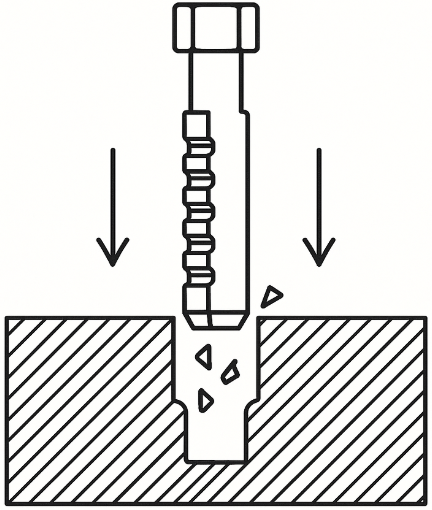
Broaching
Broaching pulls or pushes a toothed tool through a predrilled pilot hole. Each tooth is progressively taller, removing incremental material until the full internal shape is formed. Geometry is defined entirely by the tool, which produces splines, keyways, and hexes with minimal cycle time and excellent repeatability.
Pros:
- Sharp internal corners and precise forms
- Fast and consistent for large runs
- Excellent dimensional control
Cons:
- Very high tooling cost
- No flexibility once broach is made
- Requires accurate pilot hole
When to use:
Use for repeatable internal features like keyways or polygonal holes in gear hubs, pulleys, or structural hardware. Economical only in volume.
Waterjet Cutting
Waterjet cutting uses a pressurized jet (up to 90,000 psi) of water mixed with abrasives like garnet to erode material on impact. The nozzle is CNC-guided to trace precise paths. As a cold process, it introduces no thermal distortion, making it safe for composites, hardened metals, or laminated materials.
Pros:
- Cold cutting - no HAZ
- Cuts nearly any material
- Capable of thick-section piercing
Cons:
- Slower than laser or drill
- Slight kerf taper
- Limited to ~1 mm minimum hole diamete
When to use:
Use when material integrity is critical (e.g. CFRP, Inconel, laminated structures), or when thermal distortion from laser is unacceptable.
2. Design for Effective Hole Layout
Hole design is not just about aesthetics or pattern symmetry, it's about mechanical integrity, manufacturability, and avoiding deformation during forming operations. The key factors include material properties (like ductility and yield strength), thickness, and the proximity of holes to bends or edges
Sheet Metal - Hole Deformation Near Bends
When holes are placed too close to a bend line, the surrounding material experiences high strain during bending. This can lead to:
- Hole elongation
- Distortion (ovalization or tearing)
- Stress concentration zones that compromise structural performance
Use of Relief Features
Hole relief slits are narrow cuts placed parallel to the bend line, extending slightly beyond the hole edge. They work because:
- They localize and control plastic deformation, channeling stress away from the hole and into a sacrificial slit area.
- They relieve internal stress during the bending process by allowing the material to flow instead of resisting it.
- They minimize distortion by separating the bending stress zone from the hole’s geometry.
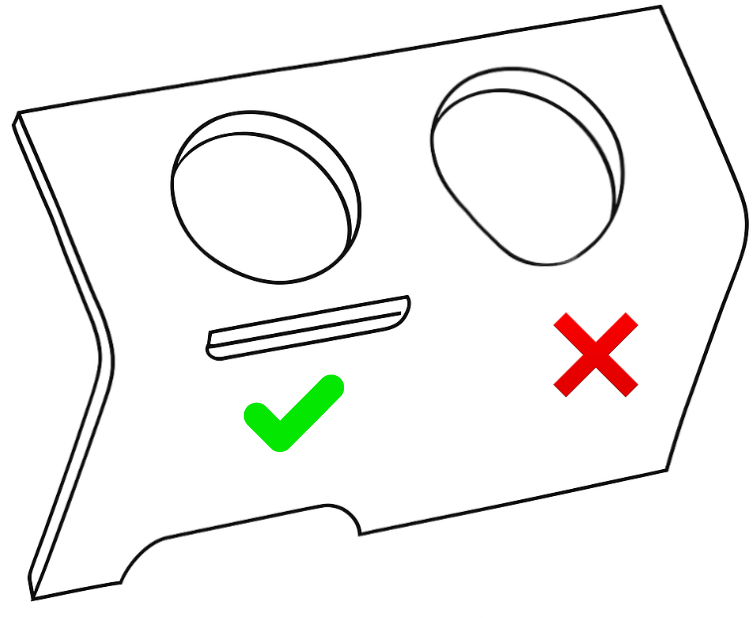
This is particularly effective in ductile materials (like low-carbon steel) where stress can propagate easily across thin walls.
Best Practice: the slit width should be 1x to 1.5x the sheet thickness, and length should extend slightly past the hole’s edge. Always consult your supplier for optimal solution tailoring.
CNC Hole Planning: Core Rules
Mess the hole placement and you’ll get weak parts, tool wear, and bad quotes. Here's how to not suck at it:
Stay Away from Edges
- Weak walls = cracks under load or vibration
- Exit blowout and burrs from unsupported drilling
- Tool deflection from low rigidity near edges
Best practice: Keep hole center ≥ 1.5× diameter from edge (2× if tapped)
Mind Hole-to-Hole Distance
- Too close = stress risers and fractures
- Thermal issues: heat builds up, distorting holes
- Thin webs flex, causing tool drift or misalignment
Ensure Tool Access - both for the manufacturer and the user, don’t assume 5-axis when you're getting 3
3. Design the Hole Bottom Wisely
Flat-bottom holes may look neat in CAD, but they’re a nightmare on the shop floor. Drills are conical by nature, trying to force a flat bottom requires specialized tools and more machining time.
Use Standard Drill Tip Angles
Drills have conical tips by design, typically 118° or 135° try using standard drill for general purposes. Only specify flat-bottom holes (also called bottoming holes) when functionally required. e.g., for press fits, seating surfaces, or when depth tolerance is critical and understanding this will increase tool changes and cost.
Add Relief Depth for Tapped Blind Holes
In blind holes, the tap cannot cut full threads all the way to the bottom due to its tapered lead. If there’s no relief, you risk incomplete threads, stripped fasteners, or poor engagement.
- For metric threads, add 1.5 × pitch of unthreaded relief below the last full thread.
- For UNC/UNF, allow at least 2–3 threads worth of run-out space.
This ensures full thread formation and lets chips evacuate without binding.
Reference: ASME B1.1 / ISO 965-1 for unified and metric threads; standard tapping charts apply.
Use Drill-Through When Possible
Blind holes always cost more than through-holes due to chip evacuation issues, risk of tool breakage, and added setup and measurement time. If your design allows it, opt for a through-hole and chamfer the exit to deburr.
4. Tolerancing: Don’t Over-Engineer the Hole
Applying unnecessarily tight tolerances is one of the most common and costly DFM mistakes.
Use fit-based tolerances only when required. Think about inspection tools: if the hole needs to be measured on a CMM instead of a simple go/no go gauge that adds time and cost.
DFM Tip: Design for Tools, Not Just CAD
- Standard hole features = fewer tool changes, faster machining, tighter tolerances.
- Avoid legacy geometry unless you’re replicating a mating component or legacy spec.
- Communicate special cases clearly on the drawing (ASME Y14.5 for feature control frames and depth callouts).
5. Understand the Cost Impact
Every hole you add impacts more than just machining time. It affects tool wear, fixturing complexity, deburring, cleaning, and inspection. Tapped holes, deep holes, or countersinks compound this - especially when they’re repeated across dozens of features. These design choices can silently double or triple part cost if not tied to real functional needs.
The right approach is to start with the intended manufacturing process and then shape your hole features to suit. Can it be drilled with a standard tool? Is a tapped hole necessary, or would a press-fit nut or insert work better? Is the tolerance or geometry critical, or just copied from a legacy design that no longer applies?
Good DFM isn't about doing less - it’s about doing only what’s necessary, with the least resistance. Let the machine drive the model, not the other way around.
Design With Manufacturability in Mind
Smart hole design is a small part of your CAD workflow, but it has a massive impact downstream. At bananaz, we help engineering teams review designs collaboratively and flag DFM issues early, before they hit the machine shop.
From AI-assisted reviews to contextual comments on specific features (like holes), bananaz helps you reduce back-and-forth, avoid costly mistakes, and build better products faster.
Final Thought: Design Like It’s Being Machined Tomorrow
Great engineering is about balancing performance with manufacturability. Next time you design a hole, think about the technology, the material, and the cost - not just the feature functionality.
At bananaz, we help mechanical engineers catch these issues early with context-aware collaboration and built-in DFM guidance. Less back-and-forth. Smarter decisions. Better products.
Want to eliminate preventable manufacturing issues before they become expensive?
Explore how bananaz can streamline your DFM process and cut design revisions by up to 90%.
.png)